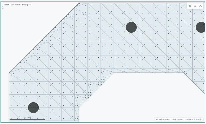
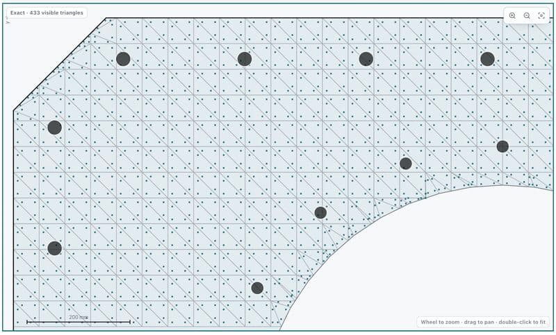
Why Use Triangular Meshes and Three Gauss Points?
Why do I use triangular mesh and 3 Gauss points in a P–M interaction solver?
In a P-M interaction solver, the mesh is not really there to solve an FEM displacement problem.
Its job is much simpler: turn ∫ σ dA ; ∫ σy dA; ∫ σx dA into numerical sums.
I triangulate the section because almost any polygon — including sections with holes — can be reduced to one simple primitive: a triangle.
But why three integration points instead of just the centroid?
Under the plane-section assumption,
ε(x,y) = ε₀ + κx y + κy x => so strain varies linearly across the section.
For an elastic material, stress is also linear.
Axial force therefore involves a first-order field: P = ∫ σ dA
But bending moment contains another coordinate: M = ∫ σy dA
so the integrand becomes second-order.
And this is the neat part:
A 3-point Gaussian rule on a triangle integrates second-order polynomials exactly.
So the three points are not arbitrary.
They are just enough to exactly recover P and M from a linear stress field inside that triangle.
When the material becomes nonlinear, they are no longer mathematically exact — but they still capture the stress gradient much better than treating the whole triangle as one fiber.
This also explains why I built a small purpose-specific triangular integration mesh instead of using a general mesher such as Gmsh.
For this problem, I don't need element stiffness matrices, nodal DOFs, or global FEM assembly.
I only need: Geometry → Triangle → Gauss points → Strain → Stress → P, M
Sometimes a smaller numerical method is more useful than a bigger numerical tool.